A two week break away from the Haflinger challange. Now back to the removed Swinging arm with the intention of taking out the fulcrum pins and replacing whats needed. Now one of the pins is turning with the swinging arm and the other is staying still with the ally casing , neither want to come out. There is evidence of wear on the clamp bolts where they come in contact with the Fulcrum pins. At that point there is a machined groove in the pin to allow the bolt to pass through.
Are the pins both right hand thread?
Now the whole assembly is soaking in diesel, parrafin, oil mix. A welder friend had made up a tool from a high tensile bolt, specially cooled to harden it and usable with a socket. So hopefully in a few days and with some heat on the job, I may have another bash at it.
Jeff
Fulcrum pins
-
Tajman
- Posts: 86
- Joined: Fri Sep 27, 2019 8:11 pm
- Location: Between Portmouth and Southampton. Hampshire .UK.
Fulcrum pins
- Attachments
-

Re: Fulcrum pins
Worst case you will have to drill them out. Maybe you could weld a bolt on to the end of the adjuster and the heat from that might break it loose.
They can be very difficult to remove when they are worn as they get a ridge and the dis-similar metals cause corrosion which locks the pins in the swing arm.
John
They can be very difficult to remove when they are worn as they get a ridge and the dis-similar metals cause corrosion which locks the pins in the swing arm.
John
Haflinger 703AP LWB 1973 - (Once owned by Lady Sutherland & Sons.) Now called "Lurch" !
Have you hit the "DONATE" button at the bottom of the page after reading this post? Many thanks if you have!!
Have you hit the "DONATE" button at the bottom of the page after reading this post? Many thanks if you have!!
-
Tajman
- Posts: 86
- Joined: Fri Sep 27, 2019 8:11 pm
- Location: Between Portmouth and Southampton. Hampshire .UK.
Re: Fulcrum pins
Thanks John.
Not having seen them out and finding the parts manual not that easy to figure out, I am still not sure what I will find if they come out.
You say they are adjusters, are you referring to the fulcrum pins with the slot on the outer surface? If you turn them less than 360, then the clamp bolt will not line up with the groove.
I can see on the inside the end with a center shiny part with a hole that I presume lets the oil lubricate the swinging arm area. It seems to show 2 seperate threaded bits on the drawing in the parts manual, One being the slotted pin, the other in the inner casing section. Phew, hope I,m making sense! There is also difference between Mk 1 and Mk 2. Dale at Haflinger Technic tells me that my 1967 Haflinger is in a period where they used parts from both models , just to confuse things . On the swinging arms I have 4 rubber seals/spacers? one on each side of the swinging arm where it enters the ally casting. So I am presuming that they are Mk 2 bits.
Well I am sure it will all become apparent when I managed to get them out, but to understand more about the the design/parts prior knowledge is a good thing I think. Thanks for your patience.
Jeff
-
AustHaflinger
- Posts: 2472
- Joined: Sun Jan 06, 2013 1:27 am
- Location: Canberra Australia
Re: Fulcrum pins
I must admit mine just screwed out no trouble at all - right hand thread - nothing special. After removing the clamping bolts in the housing (as you have done in your pic) try putting a wedge in the housing to open the housing up a little and then unscrewing the pins. Yours look the same as mine.
Garry
Garry
Haflinger 700AP (73)
Range Rover Sport TDV6 (07)
Landrover FC 101 (77)
Landrover Series 1 SWB Station Wagon (57)
Landrover Series 1 SWB (57)
Jaguar E-type Roadster V12 (71)
Jaguar XJ12C (76)
Range Rover Sport TDV6 (07)
Landrover FC 101 (77)
Landrover Series 1 SWB Station Wagon (57)
Landrover Series 1 SWB (57)
Jaguar E-type Roadster V12 (71)
Jaguar XJ12C (76)
Re: Fulcrum pins
Be very careful about trying to open up the slot - the Aluminium will be very brittle by now so will snap off if you are too enthusiastic! A wedge that has a taper on it that open it by a couple of Thou should be sufficient and heat the casting first.
I would be planning to replace everything so damaging the rubber seals or having to drill the pins out does not stop you doing things.
The pins are originally just round, but after being fitted can wear into an oval. Turning them 90 degrees thus takes out some of the wear. As they are threaded, you would turn them anti-clockwise and the slot in them is wide enough to allow the bolt to go back in.
You can not mix the MKI and MKII pins and bushes up - i.e. MKI pin into MKII bush, but you could fit the complete kit to an axle i.e. MKI pin and bush into one side of the diff plate and axle. I think it would be better to fit new kits to both side of an axle rather than mix and match.
John
Haflinger 703AP LWB 1973 - (Once owned by Lady Sutherland & Sons.) Now called "Lurch" !
Have you hit the "DONATE" button at the bottom of the page after reading this post? Many thanks if you have!!
Have you hit the "DONATE" button at the bottom of the page after reading this post? Many thanks if you have!!
Re: Fulcrum pins
We removed mine but cutting a slot in a surplus "socket" and then dropping a square bit of metal in the slot (& tack welded it in). Sort of made a giant screwdriver head, and we were able to turn it with the normal socket set handle. Worked a treat 
- Attachments
-
Julian B
W Sussex, UK
| '62 Early Series I SWB | '72 Series II LWB |
| '56 Citroën Traction Avant |
W Sussex, UK
| '62 Early Series I SWB | '72 Series II LWB |
| '56 Citroën Traction Avant |
-
ogdenenterprise
- Posts: 433
- Joined: Sun Jan 06, 2013 7:40 am
- Location: Cairns , Australia
Re: Fulcrum pins
I was advised by Andrew Davidson, (RIP) if they were very tight to use a socket like Julian's photo and a T bar, then put a large ball bearing in the dimple of the T bar and use a G clamp over the swinging arm to hold everything in place. I tried it and it worked for me,
obviously you have to tighten it up but you will get a small amount of movement with it spinning on the ball bearing just keep slackening the G clamp as it starts to screw out.
Dave
obviously you have to tighten it up but you will get a small amount of movement with it spinning on the ball bearing just keep slackening the G clamp as it starts to screw out.
Dave
Re: Fulcrum pins
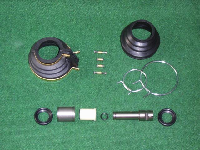
Picture of the early type fulcrum pins -later ones had a screw thread o them:
https://www.autoquariat.at/Bilder/ueber ... ss/3_0.jpg
https://www.autoquariat.at/shop/hafling ... y7wm_VGFBo
So later one have to be screwed out. I like the idea posted above of a big G clamp to keep the pressure on the screwdriver end so it stays in the slot. You could also try an Impact drive as you are going to have to replace the pins and bushes it doesn't really matter if yo damage the top of the fulcrum pin.
John
Haflinger 703AP LWB 1973 - (Once owned by Lady Sutherland & Sons.) Now called "Lurch" !
Have you hit the "DONATE" button at the bottom of the page after reading this post? Many thanks if you have!!
Have you hit the "DONATE" button at the bottom of the page after reading this post? Many thanks if you have!!
-
Tajman
- Posts: 86
- Joined: Fri Sep 27, 2019 8:11 pm
- Location: Between Portmouth and Southampton. Hampshire .UK.
Re: Fulcrum pins
Thanks everyone for suggestions and links.
I have ordered a Proto J5444A Drag link socket that looks like it might do the job. Its just over size but I should be able to grind it down. I have cramps so will try that idea.
Been busy getting the floor pan ready for shot blasting.
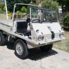
See attached picture with it piggybacking on my Volvo Laplander ready to go tomorrow.
Cheers Jeff
I have ordered a Proto J5444A Drag link socket that looks like it might do the job. Its just over size but I should be able to grind it down. I have cramps so will try that idea.
Been busy getting the floor pan ready for shot blasting.
See attached picture with it piggybacking on my Volvo Laplander ready to go tomorrow.
Cheers Jeff
- Attachments
-
Re: Fulcrum pins
Two things occur to me at this point.
1. Cab you get that drag link socket in a version designed for an impact driver?
2. Have a long chat with who ever is gong to "shot blast" your platform - the metal is not very thick to start with and where it is rusty will be paper thin. Better to get it soda blasted or vapour blasted or coconut / walnut shell blasted as it is kinder to the metal.
Show us what you come up with as far as getting the fulcrum pins out. i.e. how you mounted the swing arm and how you held the drag link socket in place, how long a breaker bar you used etc. It would all be useful information for the next person who has to deal with them.
John
Haflinger 703AP LWB 1973 - (Once owned by Lady Sutherland & Sons.) Now called "Lurch" !
Have you hit the "DONATE" button at the bottom of the page after reading this post? Many thanks if you have!!
Have you hit the "DONATE" button at the bottom of the page after reading this post? Many thanks if you have!!
-
Tajman
- Posts: 86
- Joined: Fri Sep 27, 2019 8:11 pm
- Location: Between Portmouth and Southampton. Hampshire .UK.
Re: Fulcrum pins
Hello .
Yes John the Drag link socket is 1/2 inch standard socket size. I,m may try my impact driver, but will need to support the ally casing in a way to minimise damage. I have found that the Autoquariat web site is well illustrated and helping me learn about the parts.
I suspect my fulcrum pins will be threaded. But the fact my Haflinger is on the cusp of Mk1 /Mk2, I,m not yet clear which parts are what. I think when I come to order, Haflinger technic will know what I need in terms of replacement bits.
I have now had several bits blasted and find they are quite simpathetic to the job in hand. There is alot of rot especially in the foot well area.
I am considering a new complete footwell replacement section. I am also considering which would be the best bank to rob to pay for it.
I will take pictures as I go along, (not of the bank robbery!) Cheers for now.
- Attachments
-
-
- Screenshot_2019-12-10 Threaded Swivel Pin (Green Mark).png (142.26 KiB) Viewed 6306 times
-
Re: Fulcrum pins
The first and second pictures of your post above are the parts you will need along with the O rings.
John
John
Haflinger 703AP LWB 1973 - (Once owned by Lady Sutherland & Sons.) Now called "Lurch" !
Have you hit the "DONATE" button at the bottom of the page after reading this post? Many thanks if you have!!
Have you hit the "DONATE" button at the bottom of the page after reading this post? Many thanks if you have!!
-
Tajman
- Posts: 86
- Joined: Fri Sep 27, 2019 8:11 pm
- Location: Between Portmouth and Southampton. Hampshire .UK.
Re: Fulcrum pins
Well slow progress with the fulcrum pins. although I have managed to get one out. Since when I have found one on the front that is turning with the swinging arm. So I am gearing up to have a go at that one. They seem to rust solid in the section with the thread. I tried drilling them, they are very hard.
I wonder how to tackle getting that arm off as it has the steering universal ball joint on as well. Do I still try to leave the shaft in place so as not to disturb the stones?
I have now found an engineering shop that has Lazer welding, milling/drilling and even spark eroding who say they can get the obstinate pins out.
In the mean time I have stripped the engine down and of course at least 2 studs broke of in the ally cylinder. I think I can sort that . I intend to take the heads off and have a look at valves etc.
Cheers for now
- Attachments
-
-
Re: Fulcrum pins
I would bite the bullet and take the front hub off as it will make the swing a much lighter. Next I would take the big “T” piece off the differential so you can undo the bolts round the outside of the plate that has the fulcrum pins as part of it.
When you pull that off - again be careful hitting it as it will likely crack or snap. If you do it carefully enough you can make sure the drive shaft stays in the diff as you remove the swing arm and plate. Please remember to drain the oil and remove and not lose the magnetic drain plug. DO NOT put it back in until everything is back together as it fouls the diff if you attempt to remove that so better safe than sorry.
Now you have the swing arm and side plate in a package which is easier to deal with particularly if you take it to an engineering shop to get them to remove the fulcrum pins.
John
Haflinger 703AP LWB 1973 - (Once owned by Lady Sutherland & Sons.) Now called "Lurch" !
Have you hit the "DONATE" button at the bottom of the page after reading this post? Many thanks if you have!!
Have you hit the "DONATE" button at the bottom of the page after reading this post? Many thanks if you have!!
-
Tajman
- Posts: 86
- Joined: Fri Sep 27, 2019 8:11 pm
- Location: Between Portmouth and Southampton. Hampshire .UK.
Re: Fulcrum pins
Thanks again John,
I have loosened the bolts on the "yoke" above the housing that holds the pins and the housing is ready to take off the diff casing. This is easier here because there is no diff lock mechanism or lever protruding like there was on the near side back , RHD.
Next I have removed the hub. No problems so far. Starting work on what I presume is the next move-that of removing the king pins. The top one I read can be removed with a 7mm bolt. Not a common size, But I manged to find a pack of 2 in Halfords M7x40. I also need one for the handbrake lever in the rear hub- also M7. So good, with the bolt threaded into the top of the top pin ,I could prize it out. The rubber gaiters look in good condition, so I assume it was a fairly recent job ( maybe 15-20 years ago!) that somebody " has been there", hence everything coming undone without to much agro. Well then I came to the bottom pin and took off the plate underneath to find a shallow head with 2 flats measuring 30 mm. Hardly enough to get a spanner/adjustable on. The top nut is M16- 24 mm spanner, which I do not have , so at present texting round mates to see who has what and how many pints it will cost me.. Confined space , no room for socket so presume a ring spanner will get on it. I noticed none of the castle nuts had split pins in, but there was plenty of grease about.
So next if I can prepare the king pin for removal i suppose I have to take the castle nut off the end of the universal joint shaft. On the drawing in the parts book, I can't see how that all connects to the shaft into the diff, Which I want to leave in situ if possible rather than tackle the dreaded stones.
See pictures. Hope this helps someone who may have to go down this route and also in turn someone who has been there able to give me some tips.
Thanks in appreciation.
Jeff
- Attachments
-
-
-
Re: Fulcrum pins
Hi Jeff,
You seem to be getting on quite well with this outer part of the axle! Basically, leave he castle nut on the drive shaft for the moment. You can take it off if you want, but you don't need to. Remove the top swivel pin but leave the smallest length in the bush just to hold the hub in place (vertical) whilst you deal with the lower one.
Lower swivel pin (also known as a king pin), needs to have the nut taken off as you already know - Yes a ring spanner is the easiest tool to use to undo it. Now you need to get the pin to come out the bottom, which can be easier said than done.....
The way I did it was to have a spanner that fits the two flats on the pin so you can twist it back and forth, then to have wedge that you can put in between the CV joint and the top of the pin. This will supply downward pressure on the pin, whilst you twist it back and forth and it will slowly be forced out of the bush. I made my wedge using three cold chisels, using the one in the middle to slide against the top and bottom ones so the only movement was cold chisel against cold chisel.
Once you have managed to get the bottom pin out and holding the whole of the hub, the top pin out as well, You can pull very carefully on the whole hub and it will pull away from the axle as it has a splined shaft which goes up the axle in to the diff and has the dreaded stone on it.
The is a funny double lipped seal just at the end of the of the axle right where it bells out to make the top and bottom arms that have the swivel pins at the end. You might want to think about replacing that except it is a very expensive oil seal and difficult to source other than through the Haflinger parts places it seems.
With the hub removed the rest of the axle including the side plate can be taken of the Diff. This is the point at which you may want another pair of hands if you want to leave the drive shaft in the Diff.... It actually wouldn't be that bad if it does come out with the axle as without the side plates and the limited access that comes from having the side plates (the hole the axle shaft goes through is quite small and if you put the axle and fulcrum pins back on, even smaller)!! With the side plates off, putting the stones on place is relatively easy, you just need to guide the axle shaft through the side plate and down the axle tube with out it coming out from the Diff - as I mentioned - another pair of hands at this stage can help!
Hope this make sense when you read it and try to follow things though....
Best of luck!
John
P.S. Your front CV joints are the early versions with the rubber gaiters, so presumably your fulcrum pins will be the early type BUT!!!! they could still be the later ones, so I think you have to go with trying to screw them out, or get them machined / spark eroded out if you can't get them to move.
Haflinger 703AP LWB 1973 - (Once owned by Lady Sutherland & Sons.) Now called "Lurch" !
Have you hit the "DONATE" button at the bottom of the page after reading this post? Many thanks if you have!!
Have you hit the "DONATE" button at the bottom of the page after reading this post? Many thanks if you have!!
-
Tajman
- Posts: 86
- Joined: Fri Sep 27, 2019 8:11 pm
- Location: Between Portmouth and Southampton. Hampshire .UK.
Re: Fulcrum pins
Thanks again. Today progress was very good and with help from another pair of hands I managed to get the hub off then the king pins out and with the u/j pulled off, and then the swinging arm removed no problems.
I have another worry that the 4 stud wheel flange on both front axles is slightly loose in the hub gear housing. With enough play that I would consider unacceptable. How do I take up this play? I am not sure if its just a case of tightening the castle nut, maybe putting in a shim or washer. I see that there is a taper spacer to house the taper roller bearings. The 4 stud wheel flange seems very close to the hub gear housing where there is a pointed triangle of metal just proud of the casing. Oh, What is that for?
Lastly , when I take the swinging arms to the engineering workshop, should they also remove, as well as the pins, the threaded bushing sort of helicoil thing that the pin screws into and that be replaced?
Thanks in anticipation.
Jeff
- Attachments
-
-
-
Tajman
- Posts: 86
- Joined: Fri Sep 27, 2019 8:11 pm
- Location: Between Portmouth and Southampton. Hampshire .UK.
Re: Fulcrum pins
Somethings I forgot to mention.
I am confident the king /swivel pins are good , no wear and plenty grease. In 2 instances there has been oil leaking from the 4 bolt plate inboard of the hub , behind which is an O ring. It could look like the main shaft oil seal is leaking at this point. The universal shaft "race with washer" Item 28 , shows no sign of wear where the seal runs on its surface. Seal looks good too.
Not sure if its worth going for a new oil seal there. I presume that's the double lipped, double the price seal mentioned.
Jeff
Re: Fulcrum pins
Jeff,
I take it that what you call the “four stud flange” is the four studs that hold the tyre rim on. If that is loose / wobbly when the hub is back together, i.e. when you put the two parts of the hub back together. Then you have found another of the wonderful design issue created by the designer(s) of the Haflinger! A favourite of mine!
The play is taken out by tightening up the bearing - you have obviously done this on other vehicles as you want to tighten up the castle nut on the shaft.... wrong! This is a Haflinger you are dealing with!
When you put the little square cover on the back of the hub which has the “O” ring on it too stop the oil coming out, you also put some “shims” in there. When you do the four nuts up, the shims are pushed against the outside ring of the wheel bearing which being a cone, tightens up against the rollers and takes out the play. Now in order to get the tension right you have a converlouted procedure to go through. It is explained in the workshop manual, but here is another explanation for you.
I think it is worth making yourself a special tool to help as you will probably do this wheel bearing setting several times during your ownership of a Haflinger. The tool is basically a rod which needs to go across two diagonal wheel studs so having a couple of flanges that fit on the two wheel studs, held in place with a couple of wheel nuts. The bar needs to be long enough to give you 20 cm from the centre of the wheel flange to a notch you can hang a weight on. Easy at home weight is a bag of sugar / 1 kg. Now you add or subtract shims till the weight on end of the rod can stay still until you push it gently, where upon the weight should drop smoothly. It’s a pain in the a** as you have to dismantle the back plate each time in order to change the shims.
You need to read this in conjunction with the workshop manuals explaination.
John
Haflinger 703AP LWB 1973 - (Once owned by Lady Sutherland & Sons.) Now called "Lurch" !
Have you hit the "DONATE" button at the bottom of the page after reading this post? Many thanks if you have!!
Have you hit the "DONATE" button at the bottom of the page after reading this post? Many thanks if you have!!
-
Tajman
- Posts: 86
- Joined: Fri Sep 27, 2019 8:11 pm
- Location: Between Portmouth and Southampton. Hampshire .UK.
Re: Fulcrum pins
Hello. Awaiting progress report from the engineers about the fulcrum pin removals. It won't be spark erosion, as they quoted around £500 for 3 pins. I realise after taking off the 4 stud back plate that the hub would move around a bit. So having read the workshop manual again, and John's advice, I have a clear picture how to take that forward.
Well I have been busy in the man shed, see photos. The engine and surround were caked in Scottish Grouse moor, where the Haffy spent many years. Dirt oil, grass etc. With so many tin components that need cleaning, degreasing, derusting and priming before painting, there is plenty to do. Onwards-----!
Well I have been busy in the man shed, see photos. The engine and surround were caked in Scottish Grouse moor, where the Haffy spent many years. Dirt oil, grass etc. With so many tin components that need cleaning, degreasing, derusting and priming before painting, there is plenty to do. Onwards-----!
- Attachments
-
-